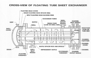
1 2 Shell And Tube Heat Exchanger Design
Most shell and tube heat exchangers have multiple passes to enhance the heat transfer. The optimum thermal design of a shell and tube heat exchanger involves the consideration of many interacting design parameters which can be summarized as follows.
Heat Transfer Equipment Processdesign
In a single pass heat exchanger the fluid goes in one end of each tube and out the other.

1 2 shell and tube heat exchanger design. These are calculated using a pressure vessel design code such as the boiler and pressure vessel code from asme american society of mechanical engineers and the british master pressure vessel standard bs 5500. Armstrong shell tube heat exchangers are suitable for higher pressure applications in oil refineries and other large chemical processes. Process fluid assignments to shell side or tube side.
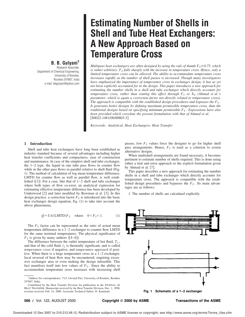
A 1 2 shell and tube heat exchanger is illustrated in figure 519. An odd number of tube passes is seldom used except the 1 1 exchanger. This refers to the number of times the fluid in the tubes passes through the fluid in the shell.
The ste module in hextran is configured in design mode by right clicking on the unit and selecting change configuration from the pop up menu. The armstrong shell tube heat exchangers provide dependable efficient heat transfer in various applications ranging from hvac to industrial installations. Setting shell side and tube side pressure drop design limits.
Use hextran to design a shell and tube heat exchanger for the kerosenecrude oil service of example 5 1 and compare the resulting unit with the one designed previously by hand. Shell and tube heat exchangers can have multiple passes such as 1 1 1 2 1 4 1 6 and 1 8 exchangers where the first number denotes the number of the shells and the second number denotes the number of passes. The mechanical design of a shell and tube heat exchanger provides information on items such as shell thickness flange thickness etc.
Shell and tube heat exchanger design is an iterative process which goes through the following steps. As you can see in a 12 heat exchanger the tube side fluid flows the entire length of the shell turns around and flows all the way back. Shell tube heat exchanger design procedure.
Selection of stream temperature specifications. The optimum thermal design of a shell and tube heat exchanger involves the consideration of many interacting design parameters which can be summarised as follows. Most shell and tube heat exchangers are either 1 2 or 4 pass designs on the tube side.
Define design parameters such as number of tube passes tube size shell id etc. Define process requirements for the new exchanger. Thermal design of a shell and tube heat exchanger typically includes the determination of heat transfer area number of tubes tube length and diameter tube layout number of shell and tube passes type of heat exchanger fixed tube sheet removable tube bundle etc tube pitch number of baffles its type and size shell and tube side.
Process fluid assignments to shell side or tube side. Selection of stream temperature specifications. Here is an example of a 1 2 1 shell pass and 2 tube passes heat exchanger.
Setting shell side and tube side pressure drop design limits. Select a suitable type of shell and tube exchanger.

Shell And Tube Heat Exchanger Wikipedia
Shell And Tube Heat Exchanger

Pdf Estimating Number Of Shells In Shell And Tube Heat Exchangers

Pv4 Series Shell Tube Heat Exchangers 3 Inch Shell Ametek
Heat Transfer By Shell And Tube Heat Exchangers


Engineers Guide Heat Transfer And Heat Transfer Equipments Heat
Temperature Approach And Temperature Cross Situations In Heat

A 1 2 Type Shell And Tube Heat Exchanger B Schematic Diagram

Design Of Multiple Shell And Tube Heat Exchangers In Series E